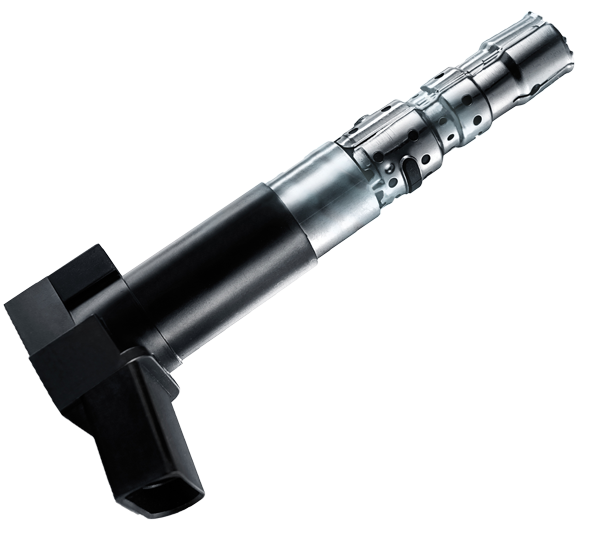
Ignition Coils in Detail
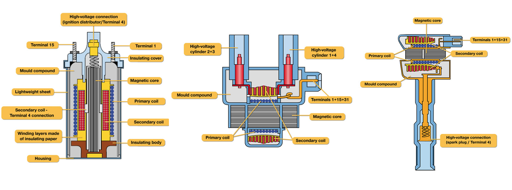
The design of an ignition coil for the petrol engine is essentially identical for all ignition coil types from a schematic perspective.
There are two coils in the interior of each ignition coil: the so-called primary coil, which is comprised of relatively thick copper wire, and the secondary coil, which is significantly longer and is produced of a relatively thin copper wire.
Ignition coils have a laminated Ferro-magnetic core, around which the primary and secondary coils are wound. The copper wire of this coil is insulated in order to prevent the voltage from jumping over from coil to coil and thus resulting in short-circuits.
Magnetic Induction and Transformation
The high-voltage pulse of an ignition coil arises in the secondary coil with the help of magnetic induction. For this purpose, the primary coil is first supplied with the battery current through the low-voltage connection of the ignition coil. A magnetic field is simultaneously formed around the primary coil. If this current flow is interrupted, the magnetic field collapses. It is this collapse which triggers a voltage pulse in the secondary coil.
The voltage pulse arising in the secondary coil is higher than the 12 volt battery voltage, which previously flowed through the primary coil. The reason: The secondary coil is wound with considerably finer wire and thus has a significantly higher number of windings than the primary coil. The so-called winding ratio is between 1:150 and 1:200, depending on the coil.
Apart from the winding ratio, there are additional factors which influence the actual level of the high-voltage pulses emitted. For example, the strength of the magnetic field arising in the primary coil plays an equally important role as that of the speed with which it collaborates. The density of the secondary coil, and the time remaining for the charge also have a strong influence on the end result.
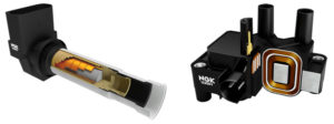
Operation Principle
An ignition coil’s primary operation function is to transform 12 volts into 30,000 volts or more. To complete this function, a complex electrical circuit is executed:
Terminal 15 of the ignition coil is connected to the positive pole of the battery via the ignition switch. Terminal 1 is connected to ground via another form of switch. As soon as the electrical circuit is closed, current flows through the primary coil. As with every conductor through which electricity flows, a magnetic field is generated (electromagnetism).
If the electrical circuit is broken, this magnetic field collapses. When this happens, an electrical pulse of 300 to 400 volts is triggered in the primary coil. The collapsing magnetic field of primary circuit induces a voltage in the secondary circuit as the lines of magnetic flux cut through the many turns of fine wire.
The fact that this induction generates a significantly higher voltage pulse is due to the winding ratio of the primary to the secondary coil. This action is known as transformation.
